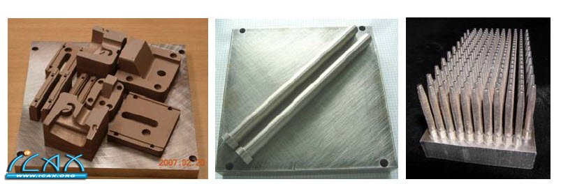
4. Materials and building strategies A variety of different metal materials are available for EOSINT M machines, and new materials are continuously being developed [4]. The most relevant material for series production tooling is a high-grade 18 Maraging 300 type steel (1.2709, X3NiCoMoTi18-9-5) which is marketed in powder form under the name EOS MaragingSteel MS1. This material is fully melted in the EOSINT M machine to produce fully dense parts with a hardness of 36 – 39 HRC as built, which can be easily post-hardened (6 hours at 490°C) to increase the hardness up to 53 – 55 HRC and produce an ultimate tensile strength of more than 1900 MPa. Tool components built in this material can be machined, eroded, polished etc. in a similar way to conventional tool steel materials. The middle and right examples of Figure 7 were built in EOS MaragingSteel MS1. In cases where lower strength and hardness are sufficient, often the material of choice for DirectTool is a proprietary bronze-nickel based alloy material called DirectMetal 20. This material has the advantage that it is very quick and easy both to build and to finish, and is therefore very popular for prototype tooling and low-volume production tooling. The high build speed is achieved partly by using processing parameters (laser scan speed etc.) which produce a partially porous structure inside the parts, whilst the outer surface region is built with higher density. The projects shown in Figure 1 through Figure 3 and Figure 6 were produced using this material. Other DMLS materials may also be useful for DirectTool applications in some cases, for example stainless steel materials are available which can be beneficial for moulding corrosive plastics. EOSINT M systems build parts on top of a metal plate called a build platform. When building mould cavities, the platform is typically integrated into the cavity design so that the DMLS geometry is melted directly onto the platform. Figure 8 (a) shows how multiple tool inserts can be built on one platform (these are components for the tool shown in Figure 6(b)). The individual inserts are cut out, typically by sawing or wire cutting, to produce inserts or onserts like those shown in Figure 1 and Figure 2. In cases where it is not convenient to integrate the platform, for example loose inserts or cooling pins, these are built on a support structure which attaches the DMLS geometry to the platform, and which is removed after building.
An example is shown in Figure 8 (b), which also shows how long parts (in this case 305 mm) can be built lying down to save time. Figure 8 (c) shows a case where standardized cooling pins were being produced as a series product by EOSINT M. Here the most efficient and cost-effective method was to build large numbers of pins standing up – in this case 200 pins fitted on one half of a build platform and could be produced fully automatically (unmannedoperation) in just 30 hours. They can be efficiently separated from the build platform by wire cutting. Aligning parts for post-machining can often be simply done using for example the side walls of the insert or other regular geometries. However, in more complex cases or where similar post-machining is often repeated, it can be beneficial to use a clamping and positioning system to save time.
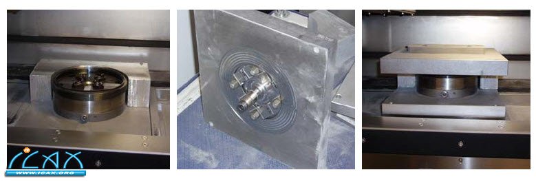
Such a system based on the widely used Erowa Powerchuck 150 system is available as a commercial option for EOSINT M systems (see Figure 9), which is particularly relevant for users who have this system on other machining stations. But various other solutions have also been implemented, according to requirements and wishes of particular users. The process software of the EOSINT M system includes a feature to enable easy alignment of the machine coordinate system to any suitable mechanical reference. 5. Summary The examples presented above are just a small selection from the very wide range of tooling applications which have already been published by EOSINT M users. Other documented tooling applications include for example vulcanization, wax injection for casting patterns, extrusion, thermofoam moulding, die casting, thixomoulding, sheet metal forming and stamping, glass forging and paper injection moulding. Also many other applications and methods of applying the technology can be considered. With the expansion in recent years from Rapid Tooling into series production tooling and advanced tooling, DMLS has established itself as a very versatile production method to complement traditional methods like CNC machining and EDM. Its ability to produce a wide range of geometries, including extremely intricate forms which are difficult to produce conventionally, rapidly and with very low effort, gives it unique advantages which have been driving the increase in the usage and acceptance of DirectTool. References [1] F. Choblet, B. Le Razer: DMLS activities at PEP – France tooling applications. In: EOS International User Meeting, Fuschlsee, 14-16th May, 2007. [2] R. Mayer: Lasergenerativ hergestellte Großserienwerkzeuge aus MS1. In: EOS International User Meeting, Fuschlsee, 14-16th May, 2007. [3] J. Tenbusch: EOS Metal Technology and Rapid Tooling. In: EOS International User Meeting, Fuschlsee, 14-16th May, 2007. [4] M. Shellabear, O. Nyrhilä: Advances in materials and properties of direct metal laser-sintered parts. In: 5th LANE, 25-28th September, 2007, Erlangen. About the authors Dr. Mike Shellabear graduated in mechanical engineering at Loughborough University of Technology, England, where he also gained his Ph.D in vibration analysis using laser interferometry. In 1991 he joined EOS, Germany, as Engineering Manager for 3D Optical Metrology, later taking over responsibility as Market DevelOPMent Manager and then Assistant to the Management Board. Following that, he was appointed Product Manager for the Direct Metal Laser Sintering (DMLS) technology and became its Vice President in 2006. He has more than 15 years of experience in the Rapid Prototyping & Manufacturing industry.
Joseph Weilhammer, studied mechanical engineering at Technische Universität München, Germany, where he did his diploma thesis about post-processing methods for DMLS tools and parts for EOS GmbH. In 1996 he joined EOS and worked there in the development department for Metal-Laser- Sintering. Then he changed to Application department and in 2007 he became Product Manager for the Direct Metal Laser Sintering (DMLS) technology. He has more than 12 years of experience in the Rapid Prototyping & Manufacturing industry.
|