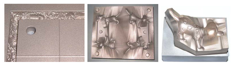
It involved the series production of a joystick assembly for a construction vehicle. 5,000 assemblies were required, each comprising 14 injection moulded parts in PA6.6 GF. By combining DirectTool with just the minimum amount of machining, all 14 injection moulds were produced and the 5,000 sets moulded within nine weeks, including a three week delay due to design changes made by the customer, and modification of one tool to compensate for asymmetric shrinkage of a circular plastic part. The six working weeks compared to 16 weeks as the fastest delivery time quoted by suppliers using conventional technology, and in additional the tooling cost only around 50 percent of the next best offer. In other cases, DirectTool is used to produce tooling for highly intricate parts, which would otherwise involve extremely complex tool path generation and machining. Figure 3 shows two examples. In both cases, the series production tooling was made by DirectTool and required no post-machining. In the case of moulds for rubber or elastomers which include undercuts, these can be easily built by DirectTool without additional effort, whereas undercuts typically involve increased complexity for machining. Although all the rapid tooling examples shown here are series production tools, the same methods are often also applied for prototype and bridge tooling.
2.2. Advanced Tooling for improving tool performance The other main motivation for using DirectTool is to use the unique design possibilities of DMLS to improve the performance of tooling, i.e. to gain benefits in the production process after the tool has been manufactured. Of course this can in many cases be combined with cost and/or time saving during the tool production, but especially for large series production, any savings in the plastic part production can justify even increased costs in tool production. The best known way of improving tool performance using DirectTool is by optimizing the design of cooling and/or tempering channels to enable lower and/or more uniform temperatures in the mould, or more rapid cooling and/or heating. This can reduce both cycle time and also scrap rates due to stresses and warpage. The result is typically increased productivity and reduced cost per part in production. With conventional machining, cooling channels are added into a tool by drilling, which restricts the cooling design to combinations of straight lines, which must all be accessible for drilling and must also avoid colliding with the forming surface, ejector pins etc. With DMLS, both the positions and shapes of cooling channels (or other elements) can be designed in a freeform way. When the channels are designed to follow the moulding surfaces of the tool, this is known as conformal cooling.
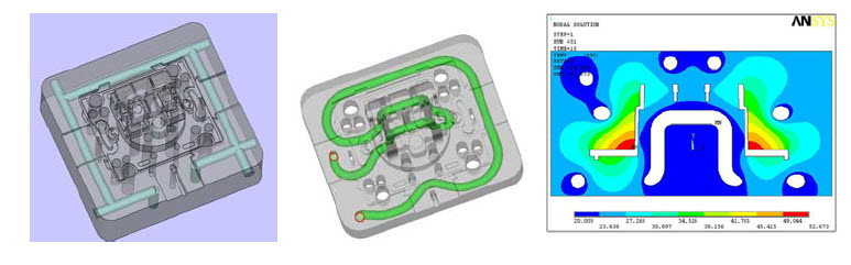
Many studies and examples have demonstrated the benefits of optimized cooling. Theoretical and practical investigations by PEP [1] have shown reductions of mould temperature by approx. 20°C (Fig. 4) and/or reduction of cycle time by 20 seconds. LBC has reported cycle time reductions of up to 60 percent and in one case a scrap rate reduction from 50 percent to zero by using DirectTool with optimized cooling [2]. The project shown in Figure 5 combined conformal cooling with a further technical benefit. The product in this case was a promotional (giveaway) golf ball, which had to be produced in large quantities at very low cost. The chosen production method was blow moulding ofextruded PP combined with elastomer injection. To avoid distortion, which was important to obtain spherical balls, a good venting of the mould during blow moulding was needed.
This was achieved by integrating venting slits into the rear side of the mould cavities, and selecting DMLS material and processing parameters to produce a slightly porous surface layer to allow gas to escape into the vents without creating any visible surface marks. It can be seen that the volume of the mould half was also kept to a minimum, thereby minimizing build time and costs. Eight such mould halves were combined to make a four-cavity tool, which was used to produce more than 20 million golf balls. Only around 50 hours build time was required, and the conformal cooling increased productivity by 20 percent. 3. Methods for applying DirectTool in tooling processes DirectTool can be applied in many different ways to achieve the benefits described above. A simple way is to build core and/or cavity inserts to fit into standard tool-frames or bolsters, in the same way that is commonly done with traditional machining. Often it is more effective, i.e. requires less effort, to mount the DirectTool core and/or cavity (including at least part of the build platform on which they have been built) directly onto the plates of the injection moulding machine, i.e. as "onserts" rather than inserts. This can be seen in Figure 1 and Figure 2.
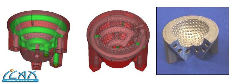
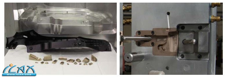
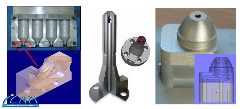
DMLS is often combined with other production methods for one tool, an approach which is often called hybrid tooling and which can be applied in many variations. For example if only one half of the tool has intricate geometry, like a mobile phone housing with a simple freeform outer (visible) surface but a complex rear (hidden) surface with ribs and clips, then it is often economical to machine the cavity (for the outer surface) whilst building the more complex core using DMLS. In other cases, only relatively small regions of a tool are so complex that they cannot be milled. In such cases it can be sensible to build small inserts using DMLS and machining pockets in the main tool for these to fit into, either as fixed or loose inserts. An example with a machined aluminium tool is shown in Figure 6 (left picture), and a similar approach can also be used with cast epoxy tooling, in which case DMLS inserts are also used for any features such as thin walls where the epoxy would not be strong enough to resist the moulding forces [3]. DMLS can also be effectively used to build various other tooling elements. The example shown in Figure 6 (right picture) used DMLS for moulding cavities, sliding inserts and also the guides for the sliders. To prevent galling, different DMLS materials were used for elements which repeatedly slide over each other. Intelligent tooling concepts also help a lot to apply optimized cooling in a cost-effective way. Figure 7 shows three examples. Figure 7 (a) shows a blow moulding tool for PE bottles. The cycle time and therefore production rate of such tools is typically limited by the cooling time for the necks of the bottles, which have the thickest cross-sections. In the case shown, small DirectTool inserts with conformal cooling were built to extract the heat from these regions more quickly, and were integrated into a standard machined production tool. In this way the cycle time was reduced from 15 seconds to just 8-9 seconds, giving a productivity improvement of approximately 75 percent, with no loss of quality. 7(b) shows a cooling core designed to be inserted into the rear of the ejector side of a mould to remove heat from the injection area. This reduced the cycle time in production by two-thirds. 7(c) shows a core with integrated conformal cooling. The dome includes a spiral-shaped cooling channel, but the core has been designed so that the lower half can be easily machined. In this way, the core was cost-effectively produced by machining the lower part, mounting it in an EOSINT M270 system and adding the top part by DMLS [2]. 0.3mm machining allowance was added for finish-machining of the outer surface.
DMLS is also sometimes used to implement design changes to existing tools or to repair worn or damaged tools. |